The shop manual says it has a positive ground but the 6 volt battery thats in it has been installed as a negative ground. Negative to positive positive to negative.
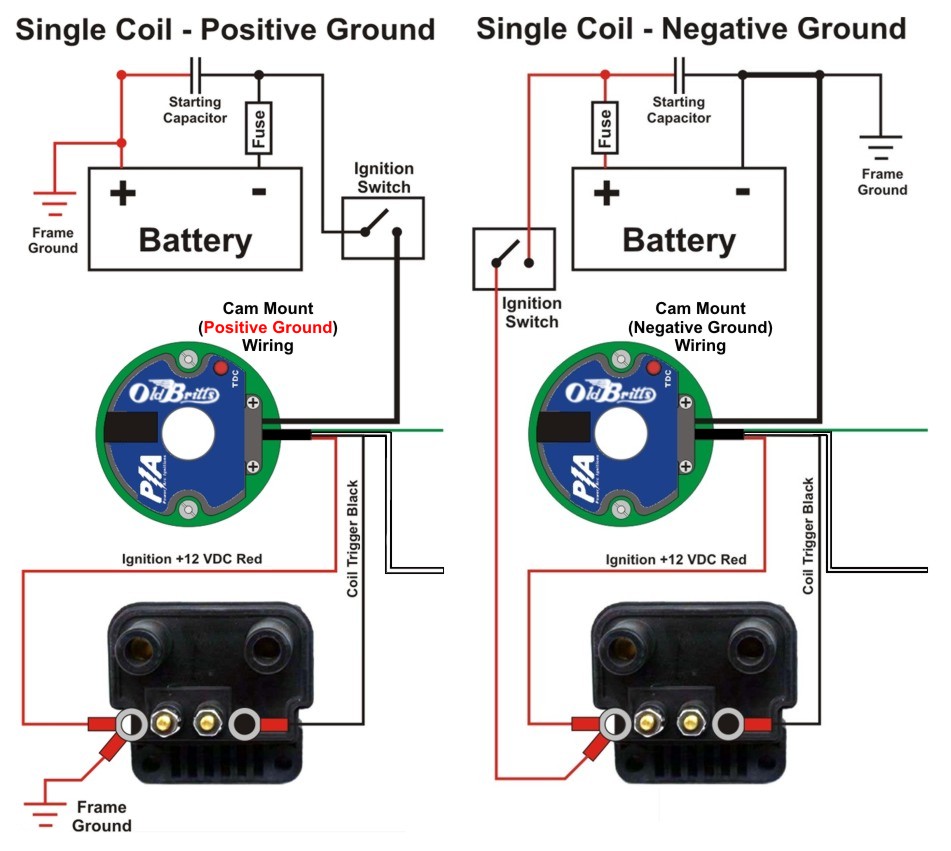
Wiring schematic for 6 volt positive ground pertronix ignitor 1188p6 original wiring is from ign switch coil term to term on 6 volt coil.

You can find out more Diagram below
6 volt neg ground coil wiring diagram. Glad to hear it hasnt hurt anything. I have a 6 volt alt am i still positive ground. See figure b 2.
This is a diagram for a p 15 but hopefully it will help a little. If your system is working fine on negative ground just buy a new battery and continue to operate that way or return to pos ground does your radio work. My question is does the wire that connects the coil to the primary post on the distributor connect to the positive side of the coil or as it is a positive ground does the wire from the distributor connect to the negative side of the coil.
The ground wire to the battery is red and the wire to the tractor is black looks like someone just put the battery in wrong. For a 12v negative system the ignition switch wire goes to the terminal on the coil. I just bought a ford jubilee with the original 6 volt system.
The wire from the. Easy to change but has anything been damaged because of. Attach the ignitor black wire to the negative coil terminal.
Wiring diagram pertronix 6 volt ignitor 1188p6 before your order one read the notes below. With the coil being correct for negative ground before and the wiring diagram from the gss 1411 76 revised service manual seems to match my tractor exactly. If you are 6v positive ground going to 12v negative you need to switch the two wires on the coil.
Term on 6 volt coil to distributor to points which are grounded on one side. If you are 6v negative ground going to 12v negative you can leave the wiring to the coil alone. I bought a high performance 6 volt coil from this site and i dont want to screw it up.
Depends on the alternator you are using. What are the issues with the battery installed as a negative ground vrs the recommended positive ground. Attach the ignitor red wire to the ignition side of resistance or any 6 volt.
Coil wire to ignition switch red wire black wire resistance wire ballast resistor the ignitor can also be installed in applications retaining the ballast resistor or resistance wire.


0 comments:
Post a Comment